USRE40533E1 - Flying pet toy - Google Patents
Flying pet toy Download PDFInfo
- Publication number
- USRE40533E1 USRE40533E1 US11/134,472 US13447205A USRE40533E US RE40533 E1 USRE40533 E1 US RE40533E1 US 13447205 A US13447205 A US 13447205A US RE40533 E USRE40533 E US RE40533E
- Authority
- US
- United States
- Prior art keywords
- toy
- frame
- members
- side members
- axis
- Prior art date
- Legal status (The legal status is an assumption and is not a legal conclusion. Google has not performed a legal analysis and makes no representation as to the accuracy of the status listed.)
- Expired - Lifetime
Links
Images


Classifications
-
- A—HUMAN NECESSITIES
- A63—SPORTS; GAMES; AMUSEMENTS
- A63H—TOYS, e.g. TOPS, DOLLS, HOOPS OR BUILDING BLOCKS
- A63H33/00—Other toys
- A63H33/18—Throwing or slinging toys, e.g. flying disc toys
-
- A—HUMAN NECESSITIES
- A01—AGRICULTURE; FORESTRY; ANIMAL HUSBANDRY; HUNTING; TRAPPING; FISHING
- A01K—ANIMAL HUSBANDRY; CARE OF BIRDS, FISHES, INSECTS; FISHING; REARING OR BREEDING ANIMALS, NOT OTHERWISE PROVIDED FOR; NEW BREEDS OF ANIMALS
- A01K15/00—Devices for taming animals, e.g. nose-rings or hobbles; Devices for overturning animals in general; Training or exercising equipment; Covering boxes
- A01K15/02—Training or exercising equipment, e.g. mazes or labyrinths for animals ; Electric shock devices ; Toys specially adapted for animals
- A01K15/025—Toys specially adapted for animals
Definitions
- the present invention relates generally to toys capable of flight while spinning about an axis.
- the present invention relates to a flying toy that is capable of flight when propelled with a spinning force.
- the apparatus includes a substantially resilient, non-circular frame that is substantially radially generated about an imaginary axis such that a higher concentration of the frame's weight is at the frame's periphery.
- the frame includes a plurality of side members with radially-extending feet members positioned between adjacent side members.
- the frame defines a central opening of which the imaginary axis is axially aligned.
- a lightweight, flexible membrane substantially covers the central opening and is attached to at least a portion of each side member.
- the side members are arched upwardly of the adjacent feed members and inwardly toward the imaginary center axis when the toy is in an at rest position.
- the membrane With the membrane, the overall resulting structure is substantially concave in shape when viewed from the side in the at rest position.
- the side members are substantially coplanar with the membrane in the at rest position.
- the invention also includes a method of use whereby when the toy of the first embodiment is launched into flight, the inherent higher concentration of the toy's weight at the periphery induces centrifugal force upon the toy thereby causing the side members to partially flatten out.
- the opposing forces of centrifugal force and resilience in the side members put the toy under tension during flight, which affects the airfoil characteristics of the toy.
- the toy is traveling at a higher velocity, the reduced airfoil is desirable.
- the resilience of the side members gradually overcomes the centrifugal force and the overall substantially concave shape is gradually resumed, which creates a thicker airfoil and increased lift while the toy descends to ground.
- the toy of the second embodiment also has a higher concentration of the toy's weight at the periphery, but will move in a boomerang-like path when the toy is propelled with a spinning force.
- FIG. 1 is a perspective view of a first embodiment of a flying toy of the present invention shown in an “at rest” state;
- FIG. 2 is a top plan view of the toy of FIG. 1 ;
- FIG. 3 is a bottom plan view thereof
- FIG. 4 is right side view thereof
- FIG. 5 is a top plan view like that of FIG. 2 but only illustrating the frame and central opening and feet shown in cross section;
- FIG. 6 is a cross section view of the toy taken substantially along lines 6 — 6 of FIG. 1 , less the membrane, and better showing the feet members;
- FIG. 7 is an enlarged perspective view of a portion of the frame connected to a foot member
- FIG. 8 is a perspective view of an alternate embodiment of ends of side members connected to a foot member
- FIG. 9 is a perspective view of another alternate embodiment of a frame portion connected to a foot member
- FIG. 10 is a view like FIG. 4 shown with an alternate embodiment of the feet members
- FIG. 11 is a bottom perspective view of an alternate foot member of FIG. 10 ;
- FIG. 12 is a top plan view of a second embodiment frame shape
- FIG. 13 is a top pan view of a third embodiment frame shape
- FIG. 14 is a top plan view of a fourth embodiment frame shape
- FIG. 15 is a top plan view of a fifth embodiment frame shape
- FIG. 16 is a perspective view of an alternate embodiment of the flying toy that is manufactured through a molding technique
- FIG. 17 is a side view of the alternate embodiment of FIG. 16 ;
- FIG. 18 is a perspective view of another alternate embodiment of the flying pet toy disclosing a frame that has an additional bowed out portion to accommodate a face for aesthetic purposes;
- FIG. 19 is a perspective view showing the flying toy of FIG. 1 in use
- FIG. 20 is a perspective view of the flying toy of FIG. 1 flattening out in its “in use” state
- FIG. 21 is a perspective view when the flying toy of FIG. 20 has returned to its substantially concave shape in its “at rest” state;
- FIG. 22 is a perspective view of another alternate embodiment of the flying toy
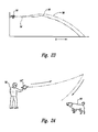
- FIG. 23 is a schematic representation of a typical flight path of the toy of FIG. 1 ;
- FIG. 24 is a schematic representation of the flight path when utilizing the invention of FIG. 22 as a boomerang.
- the toy 10 includes a resilient, non circular, frame 12 that is substantially generated about Axis A—A.
- the frame 12 is comprised of a plurality of resilient side members 14 positioned between radially-extending feet members 16 .
- each side member is positioned such that a central portion 13 of each side member is raised above its adjacent feet members 16 when the toy 10 is in a quiescent or “at rest” state.
- the frame forms a periphery in which a central opening 18 is defined.
- Axis A—A is axially-aligned within central opening 18 .
- Each foot member 16 has a bottom portion 20 that is the nadir of the toy in the at rest state. These bottom portions of each foot member substantially reside in a nadir plane P n when the toy 10 is in the at rest position, as shown in FIGS. 1-4 . It should be understood that given the imprecise manufacturing techniques and use, of which are further discussed, below, the feet members at any given time may be not equally coplanar. Thus, the nadir plane is a general guideline (substantially coplanar) as opposed to an absolute value.
- Each side member 14 is positioned in such a way relative to the adjoining feet members as to define an essentially overall concave-shaped frame as best illustrated in FIG. 6 .
- each side member 14 is arched upwardly relative to the adjoining feet members and inwardly toward Axis A—A.
- the overall concave-shape of the side members can be accomplished, in one embodiment, through flexible, resilient tube members 21 that have preset arches and that such arched tube members 21 are attached at the feet members 16 .
- Another embodiment would be to use a continuous formed member that defines the shape of the frame.
- the side members may be made from flexible, resilient, tube members 21 .
- the term “tube member” does not necessarily require a cylindrical-shaped member having a circular cross section, although that is the preferred embodiment illustrated in FIGS. 5-6 and as illustrated in FIGS. 7-9 .
- tube member 21 can have any polygonal, amorphous, arcuate, or airfoil cross section, such as oblong, square, rectangular, triangular, etc.
- the side members may be made from flexible rod, foam, rope, rubber, thermoplastics urethanes, or any material that will provide sufficient resilience to support the raised sides while allowing centrifugal force to partially flatten the device while in flight.
- the weight of the toy is concentrated at the periphery.
- a substantial portion of the overall weight of the toy resides between the concentric circles C 1 and C 2 , which is generally 50% or more of the overall toy.
- a higher concentration of weight of the frame inherently resides at the periphery between C 1 and C 2 at the feet members 16 and a portion of the adjacent side members 14 that radially extend outwardly from Axis A—A.
- each foot member may include an additional weighted pad 22 , which may be a synthetic rubber pad.
- the weighted pad 22 may be made from natural rubber or any other tough and abrasion-resistant material.
- the additional weight adds gyroscopic stability (e.g. making the toy fly in a substantially straight path) and aids the toy to land upright, i.e. on its feet after flight, which is desirable. Additionally, the rubber pad added to each foot member minimizes abrasion damage to the toy when landing on a hard surface, such as a pavement.
- adjacent side members 14 can be joined to its corresponding adjoining foot member 16 by a variety of means.
- ends 24 of side member 14 terminates within the adjoining foot member.
- ends 24 of adjacent side members may be adhered or sewn atop of the foot member, or sewn and secured between the foot member and an outside layer of fabric or other membrane material (discussed further below).
- Ends 24 from adjacent side members 14 may be positioned together, as illustrated in FIG. 7 , or apart as illustrated in FIG. 9 .
- two adjacent ends 24 may be connected by another tubular rod 26 , as illustrated in FIG. 8 .
- the pad of the previous paragraph is not a requirement for the invention to function properly.
- the feet members 16 may consist of the joined ends of the side members or of the peripheral ends of the frame that may be one unitary structure as already mentioned above.
- the foot member 16 may have a relatively gently sloping, curved outer surface 30 . If the weighted rubber pad 22 is utilized, the sloped outward curved surface can easily be formed from the rubber material. The gentle slope of the foot member provides a sufficient planar area 32 to land after flight while still retaining the toy's upright, essentially concave shape.
- FIGS. 10 and 11 discloses another embodiment where the bottom portion of each foot member 16 ′ defines a substantially concave-shaped opening or indentation. The concave surface on the underside of each foot member assists in providing additional lift while the toy is in spinning flight.
- a flexible membrane 36 covers central opening 18 .
- this membrane may be a lightweight, but sturdy fabric, such as a woven nylon material.
- the flexible membrane is a urethane coated fabric for durability.
- any fabric, felt, lightweight foil, thermoplastic, urethane, rubber, latex, foam, or other flexible material, can be used.
- the overall shape of the toy is generally concave in nature. The highest point, or pinnacle, on the substantially concave-shaped toy is in a pinnacle plane P p , which is substantially parallel to the nadir plane.
- the highest point on the toy is either the pinnacle of the concave point on the side members or, depending on the slackness of the membrane, a point on the membrane within the central opening.
- the toy 10 is shown where the bottom portions of the weighted feet are in the nadir plane P n , the pinnacle of the concave portion of the side member shown is the highest point of the toy and is in the pinnacle plane P p , and Axis A—A is substantially perpendicular to both planes.
- the flying toy apparatus shape of the present invention is not dependent on the four side members as illustrated in FIGS. 1-4 . Rather, any non-circular shape with arced sides members relative to the adjoining feet members may suffice.
- the reader is referred to top plan views showed in FIGS. 12-15 .
- an alternate embodiment of the toy 10 ′ may be molded as a unitary structure.
- the frame 12 ′, including side members 14 ′ and feet members 16 ′, and membrane 36 ′ may all be molded as a unitary structure.
- Any common molding technique such as blow molding, compression molding, injection molding, thermo-forming, or other techniques such as over-molding onto pre-molded components or fabrics, or combination thereof, may also be used.
- the molded flying toy of the present invention provides flexibility and resiliency, and, particularly, sufficient resilience in the side members to return the toy to its overall generally concave when the toy is at rest, and sufficient flexibility to allow centrifugal force induced by the weight of the spinning feet to partially flatten out the toy while in flight.
- the toy 10 may include a side member 38 bowed outwardly from Axis A—A on one side 38 to accommodate a face, or other design feature, for aesthetic purposes and/or product configuration purposes.
- a side member 38 bowed outwardly from Axis A—A on one side 38 to accommodate a face, or other design feature, for aesthetic purposes and/or product configuration purposes.
- an anthropomorphic animal figure may be added to the membrane and frame for user interest, such as a squirrel (head shown at 40 , body 42 , and four legs 44 to replicate a “flying squirrel”) and of which is the subject of the Applicant's U.S. Design Pat. No. D461,603, granted Aug. 13, 2002, and entitled “Flying Pet Toy” from an application filed Oct. 10, 2001.
- the present invention can encompass variations in overall size.
- the embodiment shown in FIG. 18 may be approximately 6-14 inches long taken as measured from one foot member to the adjacent foot member.
- the present invention encompasses a smaller version, such as one being less than 6 inches as measured from the standards discussed directly above. The smaller version would be ideally suited for office desk toy or promotional giveaway.
- the toy 10 may also include multicolor stripes, such as shown at 46 and 48 in FIG. 18 , where “ 46 ” enumerates one color and “ 48 ” enumerates another contrasting color.
- the colors of the membrane/frame spinning about Axis A—A can be visually interesting to the user, such as a child or pet, thus, encouraging further play.
- FIGS. 19-21 Use of the toy is best illustrated in FIGS. 19-21 .
- a user 50 can grab a foot member or a side member (with or without a portion of the adjacent membrane).
- the toy is flung from the user's hand 52 in such a manner as to propel they toy with a spinning force in a relatively horizontally-oriented plane P.
- the feet members, side members, and membrane spin about Axis A—A, while the toy and Axis A—A move relative to the ground a distance X.
- FIG. 23 A schematic view of a typical flight path is shown in FIG. 23 at 54 .
- the produced lift is shown at time point 56 .
- a typical flight path 58 is illustrative of a light wind gust.
- FIG. 22 An alternate embodiment of the toy 10 ′′ is illustrated in FIG. 22 where the side members 14 ′′ are not raised.
- the “flattened” embodiment of the toy is comparable to the view in FIG. 20 , but the side members and feet members do not form a substantially concave overall shape as viewed from the side in an “at rest” state. Without the variable changing airfoil, which exists in the overall concave-shaped embodiment, the toy is prone to gyroscopic precession. This particular embodiment is well-suited for boomerang-like applications.
- FIG. 24 illustrates a schematic (plan) view of an alternate flight path when the toy of FIG. 22 is used as a boomerang.
- the toy may be molded to achieve the shape and characteristics of the present invention.
- Other ways known to those of ordinary skill the art will be apparent as to how to produce the invention, such as through cut and sew techniques.
- the membrane 36 may be sewn in sections. This can be done not only to provide the aesthetic color stripes, discussed above, but also to add strength and flexibility to the membrane and to provide a substantially concave shape to the membrane.
- the membrane may be made from one or more fabric layers.
- an internal rectangular seamed box 62 defines the area where only a single layer of material covers central opening 18 , rather than the double thickness layer elsewhere in the central opening area.
- Axis A—A is positioned within the single fabric layer of box 62 .
- the shape of the “box” is not important. The reduced weight of the membrane at the Axis, along with the higher concentration of the weight at the periphery, increases the spinning inertia about the Axis A—A during spinning flight, as well as maintaining gyroscopic stability.
- Advantages of the present invention include a superior flying toy that easily spins about its axis, lands upright such that it is easy to grip (by a user's hand or a pet's teeth).
- the illustrated embodiments are only examples of the present invention and, therefore, are non-limitive. It is to be understood that many changes in the particular structure, materials, and features of the invention may be made without departing from the spirit and scope of the invention. Therefore, it is the Applicant's intention that his patent rights not be limited by the particular embodiments illustrated and described herein, but rather by the following claims interpreted according to accepted doctrines of claim interpretation, including the Doctrine of Equivalents and Reversal of Parts.
Abstract
Description
Claims (38)
Priority Applications (1)
| Application Number | Priority Date | Filing Date | Title |
|---|---|---|---|
| US11/134,472 USRE40533E1 (en) | 2001-10-10 | 2005-05-19 | Flying pet toy |
Applications Claiming Priority (3)
| Application Number | Priority Date | Filing Date | Title |
|---|---|---|---|
| US32947201P | 2001-10-10 | 2001-10-10 | |
| US10/243,068 US6565404B2 (en) | 2001-10-10 | 2002-09-12 | Flying pet toy |
| US11/134,472 USRE40533E1 (en) | 2001-10-10 | 2005-05-19 | Flying pet toy |
Related Parent Applications (1)
| Application Number | Title | Priority Date | Filing Date |
|---|---|---|---|
| US10/243,068 Reissue US6565404B2 (en) | 2001-10-10 | 2002-09-12 | Flying pet toy |
Publications (1)
| Publication Number | Publication Date |
|---|---|
| USRE40533E1 true USRE40533E1 (en) | 2008-10-07 |
Family
ID=26935558
Family Applications (2)
| Application Number | Title | Priority Date | Filing Date |
|---|---|---|---|
| US10/243,068 Ceased US6565404B2 (en) | 2001-10-10 | 2002-09-12 | Flying pet toy |
| US11/134,472 Expired - Lifetime USRE40533E1 (en) | 2001-10-10 | 2005-05-19 | Flying pet toy |
Family Applications Before (1)
| Application Number | Title | Priority Date | Filing Date |
|---|---|---|---|
| US10/243,068 Ceased US6565404B2 (en) | 2001-10-10 | 2002-09-12 | Flying pet toy |
Country Status (6)
| Country | Link |
|---|---|
| US (2) | US6565404B2 (en) |
| EP (1) | EP1310162B1 (en) |
| AT (1) | ATE292504T1 (en) |
| CA (1) | CA2404877C (en) |
| DE (1) | DE60203585T2 (en) |
| DK (1) | DK1310162T3 (en) |
Cited By (6)
| Publication number | Priority date | Publication date | Assignee | Title |
|---|---|---|---|---|
| US20080224412A1 (en) * | 2007-03-14 | 2008-09-18 | Donna Newman-Bluestein | Apparatus and method to facilitate group exercise and movement |
| US20110012309A1 (en) * | 2009-07-15 | 2011-01-20 | David Schreff | Aerodynamic sports toy, game and method of play |
| US20110209670A1 (en) * | 2010-02-26 | 2011-09-01 | Mcelwain Scott A | Pet entertainment device and system |
| US8393300B2 (en) | 2010-12-09 | 2013-03-12 | The Kong Company, Llc | Pet toy with flexible body and rope support configurations |
| US20180085678A1 (en) * | 2016-09-23 | 2018-03-29 | Connor Lee Middleton | Self-propelled toy glider |
| US11712637B1 (en) | 2018-03-23 | 2023-08-01 | Steven M. Hoffberg | Steerable disk or ball |
Families Citing this family (17)
| Publication number | Priority date | Publication date | Assignee | Title |
|---|---|---|---|---|
| US20060189246A1 (en) * | 2003-02-15 | 2006-08-24 | Stark Steven P | Disc spinning device |
| US20040166764A1 (en) * | 2003-02-15 | 2004-08-26 | Stark Steven Patrick | Flexible flying disc |
| ITTO20030767A1 (en) * | 2003-10-02 | 2005-04-03 | Davide Gastaldi | TRIPOD STRUCTURAL ELEMENT AND RETICULAR STRUCTURE |
| WO2007038449A1 (en) * | 2005-09-23 | 2007-04-05 | William Cowles | Throwing disc |
| US20070123367A1 (en) * | 2005-11-28 | 2007-05-31 | Brady Michael J | Golf ball locator |
| WO2007126405A2 (en) * | 2006-03-30 | 2007-11-08 | University Of Florida Research Foundation Inc. | Airfoil for micro air vehicle |
| US7487937B2 (en) * | 2006-03-30 | 2009-02-10 | University Of Florida Research Foundation, Inc. | Airfoil for micro air vehicle |
| US8858289B2 (en) * | 2009-04-20 | 2014-10-14 | Nite Ize, Inc. | Lighted flying disc |
| FR2985436B1 (en) * | 2012-01-06 | 2018-04-06 | Flype | ROTATING OBJECT IN A FLOW OF AIR, SUITABLE FOR FUN USE. |
| US10609905B2 (en) * | 2014-03-11 | 2020-04-07 | Little Big Cat, Inc. | Pet toy with telescoping wand with retractable cord apparatus |
| US10015951B2 (en) * | 2014-05-01 | 2018-07-10 | Bow Wow Labs, Inc. | Pet treat holder and safety device |
| US9630121B1 (en) * | 2015-05-19 | 2017-04-25 | Marcus Bridgewater | Modular flying disc |
| US10575499B2 (en) | 2015-09-22 | 2020-03-03 | Make Ideas, LLC | Pet toy with layered armor and method for entertaining an animal with the pet toy |
| US10814975B1 (en) | 2016-11-09 | 2020-10-27 | James Dean Zongker | Fixed-wing flying device configured to fly in multiple directions |
| US11503806B1 (en) | 2018-06-12 | 2022-11-22 | Make Ideas Llc | Dog dental device with brushes extending through compressible outer shell |
| US11612139B2 (en) | 2019-12-12 | 2023-03-28 | Make Ideas, LLC | Animal-operated oral gel delivery and diaphragm pump device for animals |
| US11577134B2 (en) * | 2021-07-07 | 2023-02-14 | Jlaser Llc | Spring ring device |
Citations (49)
| Publication number | Priority date | Publication date | Assignee | Title |
|---|---|---|---|---|
| US1345067A (en) * | 1920-03-22 | 1920-06-29 | Bastian Bros Company | Toy umbrella |
| US3565434A (en) | 1965-10-18 | 1971-02-23 | James F Liston | Boomerang with adjustable-pitch blades |
| US3931971A (en) * | 1974-05-10 | 1976-01-13 | Harvey Bobbie S | Projectile having indented surface areas |
| USD243029S (en) | 1975-06-09 | 1977-01-11 | Crew Richard P | Boomerang |
| US4104822A (en) | 1976-12-03 | 1978-08-08 | Rodgers Henry Wendell | Rotating circular airfoil |
| US4115946A (en) | 1976-10-07 | 1978-09-26 | Daniel Vukmirovich | Flexible discus device |
| US4174834A (en) | 1977-10-03 | 1979-11-20 | Aldo De Martino | Stick-propelled disk game |
| US4203249A (en) | 1978-02-21 | 1980-05-20 | Bohm Hans Peter | Flying saucer or throwing disk used in sports games |
| US4222573A (en) | 1979-04-26 | 1980-09-16 | Adler Alan John | Boomerang |
| US4223473A (en) | 1978-11-30 | 1980-09-23 | Brown James L | Soft flying game disc |
| US4241533A (en) | 1979-03-16 | 1980-12-30 | Newsome Reginald W | Aerial toy glider |
| US4288942A (en) | 1979-08-03 | 1981-09-15 | Nicholl Thomas H | Aerodynamic device |
| US4290226A (en) | 1979-11-15 | 1981-09-22 | Stauffer Allen R | Flexible flying disc toy |
| US4307535A (en) | 1980-03-24 | 1981-12-29 | Stanley W. Wilcox | Aerodynamic device |
| US4370824A (en) | 1977-02-23 | 1983-02-01 | Herbert Resnicow | Aerial device |
| US4425734A (en) | 1980-04-24 | 1984-01-17 | Peter Bauer | Flat-packaged air glider toy |
| US4669996A (en) | 1985-10-07 | 1987-06-02 | Bershak William P | Recreational flying ring having primary and secondary airfoils |
| US4820230A (en) | 1987-01-06 | 1989-04-11 | Richards Marvin D | Tossing ring and saucer |
| US4854907A (en) | 1988-01-27 | 1989-08-08 | Holmes Stephen E | "ESU" flying ring |
| US4915661A (en) | 1988-02-05 | 1990-04-10 | Tedco, Inc. | Disc toy |
| US4944707A (en) | 1989-03-15 | 1990-07-31 | Oddzon Products, Inc | Ring-like flying toy |
| US4973284A (en) | 1989-11-24 | 1990-11-27 | Sassak Mark S | Combination flying disc and doll |
| US5020808A (en) | 1990-01-11 | 1991-06-04 | Richards Marvin D | Tossing ring |
| USD322642S (en) | 1989-09-08 | 1991-12-24 | Crew Richard P | Boomerang |
| US5078637A (en) | 1991-03-01 | 1992-01-07 | Carpe Diem Imagineering, Inc. | Flexible flying disc with edge tube |
| US5080624A (en) | 1990-11-30 | 1992-01-14 | Brinker Sheridan F | Multi disc flying toy featuring lift producing fins |
| US5116275A (en) | 1989-11-24 | 1992-05-26 | Sassak Mark S | Tossable flying disc |
| US5261846A (en) | 1992-10-09 | 1993-11-16 | Rose American Corporation | Flexible flying disk toy |
| US5326299A (en) | 1992-03-23 | 1994-07-05 | Jasinski Gene M | Flexible disc toy for singular and multiple flights and bounces |
| US5340347A (en) | 1988-06-24 | 1994-08-23 | Yenerich Philip C | Flying toy |
| US5358440A (en) | 1994-01-06 | 1994-10-25 | Yu Zheng | Collapsible flying disc |
| US5362067A (en) | 1994-02-16 | 1994-11-08 | Nelson Webb T | Throwable toy having a ring arrangement of many extended fibers having one end of each fiber held with other fiber ends in a set of twisted wires arranged and joined together in a ring |
| US5655777A (en) | 1995-10-30 | 1997-08-12 | Neading; Ryan R. | Weighted radially-armed flexible and spinnable throwing object |
| US5785618A (en) * | 1997-05-22 | 1998-07-28 | Coleman; Thomas J. | Webbing used for a tossing game between players |
| US5800237A (en) * | 1997-02-12 | 1998-09-01 | Cummings; Charles A. | Flying segmented ring |
| US5816879A (en) * | 1995-06-08 | 1998-10-06 | Kyame; Joseph J. | Flingable flying disc toy with a central opening with inwardly directed vanes |
| US5853311A (en) * | 1996-03-22 | 1998-12-29 | Bartholomew; Mark | Multi-layered flying disk |
| US5873761A (en) * | 1996-04-16 | 1999-02-23 | Johnson; Michael W. | Aerodynamic toy |
| US5901926A (en) * | 1997-08-07 | 1999-05-11 | Patent Category Corp. | Collapsible flying structures |
| US5954417A (en) * | 1998-09-03 | 1999-09-21 | Mai; Kuei Ying | Umbrella with alert device |
| US6050871A (en) * | 1994-04-19 | 2000-04-18 | Applied Elastomerics, Inc. | Crystal gel airfoils with improved tear resistance and gel airfoils with profiles capable of exhibiting time delay recovery from deformation |
| US6109282A (en) * | 1998-10-21 | 2000-08-29 | Yoon; Young W. | Self-erecting loop structure |
| US6113453A (en) | 1997-11-07 | 2000-09-05 | Stuffelbeam; Kim | Flying toy apparatus and assembly method |
| US6174214B1 (en) * | 1998-09-16 | 2001-01-16 | Coopsort International Ltd. | Flexible waterproof flying disc and method of manufacture thereof |
| US6293879B2 (en) * | 1999-02-03 | 2001-09-25 | Charles D. Moore | Multi-disk boomerang |
| US20010034274A1 (en) * | 2000-02-10 | 2001-10-25 | Victor Tulipani | Portable soccer goal apparatus |
| US6390879B1 (en) | 1998-12-31 | 2002-05-21 | Donald Spector | Flying disc toy |
| US6443862B1 (en) * | 1999-11-03 | 2002-09-03 | John H. Darnell | Returning flying polygon |
| US6511390B2 (en) * | 2001-06-19 | 2003-01-28 | Bae-Kyun Kim | Sports ball net assembly |
Family Cites Families (4)
| Publication number | Priority date | Publication date | Assignee | Title |
|---|---|---|---|---|
| US5234367A (en) * | 1992-04-20 | 1993-08-10 | Decesare John J | Articulated gliding ring |
| US6179737B1 (en) * | 1995-01-09 | 2001-01-30 | Alan J. Adler | Flying disc |
| US5674102A (en) * | 1996-10-28 | 1997-10-07 | Lin; Jerome | Shape-changing flying saucer |
| USD461603S1 (en) | 2001-10-10 | 2002-08-13 | Mark Oblack | Flying pet toy |
-
2002
- 2002-09-12 US US10/243,068 patent/US6565404B2/en not_active Ceased
- 2002-09-25 CA CA002404877A patent/CA2404877C/en not_active Expired - Lifetime
- 2002-09-27 EP EP02021847A patent/EP1310162B1/en not_active Expired - Lifetime
- 2002-09-27 DE DE60203585T patent/DE60203585T2/en not_active Expired - Lifetime
- 2002-09-27 AT AT02021847T patent/ATE292504T1/en not_active IP Right Cessation
- 2002-09-27 DK DK02021847T patent/DK1310162T3/en active
-
2005
- 2005-05-19 US US11/134,472 patent/USRE40533E1/en not_active Expired - Lifetime
Patent Citations (51)
| Publication number | Priority date | Publication date | Assignee | Title |
|---|---|---|---|---|
| US1345067A (en) * | 1920-03-22 | 1920-06-29 | Bastian Bros Company | Toy umbrella |
| US3565434A (en) | 1965-10-18 | 1971-02-23 | James F Liston | Boomerang with adjustable-pitch blades |
| US3931971A (en) * | 1974-05-10 | 1976-01-13 | Harvey Bobbie S | Projectile having indented surface areas |
| USD243029S (en) | 1975-06-09 | 1977-01-11 | Crew Richard P | Boomerang |
| US4115946A (en) | 1976-10-07 | 1978-09-26 | Daniel Vukmirovich | Flexible discus device |
| US4104822A (en) | 1976-12-03 | 1978-08-08 | Rodgers Henry Wendell | Rotating circular airfoil |
| US4104822B1 (en) | 1976-12-03 | 1986-10-14 | ||
| US4104822B2 (en) | 1976-12-03 | 1989-06-27 | Rotating circular airfoil | |
| US4370824A (en) | 1977-02-23 | 1983-02-01 | Herbert Resnicow | Aerial device |
| US4174834A (en) | 1977-10-03 | 1979-11-20 | Aldo De Martino | Stick-propelled disk game |
| US4203249A (en) | 1978-02-21 | 1980-05-20 | Bohm Hans Peter | Flying saucer or throwing disk used in sports games |
| US4223473A (en) | 1978-11-30 | 1980-09-23 | Brown James L | Soft flying game disc |
| US4241533A (en) | 1979-03-16 | 1980-12-30 | Newsome Reginald W | Aerial toy glider |
| US4222573A (en) | 1979-04-26 | 1980-09-16 | Adler Alan John | Boomerang |
| US4288942A (en) | 1979-08-03 | 1981-09-15 | Nicholl Thomas H | Aerodynamic device |
| US4290226A (en) | 1979-11-15 | 1981-09-22 | Stauffer Allen R | Flexible flying disc toy |
| US4307535A (en) | 1980-03-24 | 1981-12-29 | Stanley W. Wilcox | Aerodynamic device |
| US4425734A (en) | 1980-04-24 | 1984-01-17 | Peter Bauer | Flat-packaged air glider toy |
| US4669996A (en) | 1985-10-07 | 1987-06-02 | Bershak William P | Recreational flying ring having primary and secondary airfoils |
| US4820230A (en) | 1987-01-06 | 1989-04-11 | Richards Marvin D | Tossing ring and saucer |
| US4854907A (en) | 1988-01-27 | 1989-08-08 | Holmes Stephen E | "ESU" flying ring |
| US4915661A (en) | 1988-02-05 | 1990-04-10 | Tedco, Inc. | Disc toy |
| US5340347A (en) | 1988-06-24 | 1994-08-23 | Yenerich Philip C | Flying toy |
| US4944707A (en) | 1989-03-15 | 1990-07-31 | Oddzon Products, Inc | Ring-like flying toy |
| USD322642S (en) | 1989-09-08 | 1991-12-24 | Crew Richard P | Boomerang |
| US4973284A (en) | 1989-11-24 | 1990-11-27 | Sassak Mark S | Combination flying disc and doll |
| US5116275A (en) | 1989-11-24 | 1992-05-26 | Sassak Mark S | Tossable flying disc |
| US5020808A (en) | 1990-01-11 | 1991-06-04 | Richards Marvin D | Tossing ring |
| US5080624A (en) | 1990-11-30 | 1992-01-14 | Brinker Sheridan F | Multi disc flying toy featuring lift producing fins |
| US5078637A (en) | 1991-03-01 | 1992-01-07 | Carpe Diem Imagineering, Inc. | Flexible flying disc with edge tube |
| US5326299A (en) | 1992-03-23 | 1994-07-05 | Jasinski Gene M | Flexible disc toy for singular and multiple flights and bounces |
| US5261846A (en) | 1992-10-09 | 1993-11-16 | Rose American Corporation | Flexible flying disk toy |
| US5358440A (en) | 1994-01-06 | 1994-10-25 | Yu Zheng | Collapsible flying disc |
| US5362067A (en) | 1994-02-16 | 1994-11-08 | Nelson Webb T | Throwable toy having a ring arrangement of many extended fibers having one end of each fiber held with other fiber ends in a set of twisted wires arranged and joined together in a ring |
| US6050871A (en) * | 1994-04-19 | 2000-04-18 | Applied Elastomerics, Inc. | Crystal gel airfoils with improved tear resistance and gel airfoils with profiles capable of exhibiting time delay recovery from deformation |
| US5816879A (en) * | 1995-06-08 | 1998-10-06 | Kyame; Joseph J. | Flingable flying disc toy with a central opening with inwardly directed vanes |
| US5655777A (en) | 1995-10-30 | 1997-08-12 | Neading; Ryan R. | Weighted radially-armed flexible and spinnable throwing object |
| US5853311A (en) * | 1996-03-22 | 1998-12-29 | Bartholomew; Mark | Multi-layered flying disk |
| US5873761A (en) * | 1996-04-16 | 1999-02-23 | Johnson; Michael W. | Aerodynamic toy |
| US5800237A (en) * | 1997-02-12 | 1998-09-01 | Cummings; Charles A. | Flying segmented ring |
| US5785618A (en) * | 1997-05-22 | 1998-07-28 | Coleman; Thomas J. | Webbing used for a tossing game between players |
| US5901926A (en) * | 1997-08-07 | 1999-05-11 | Patent Category Corp. | Collapsible flying structures |
| US6113453A (en) | 1997-11-07 | 2000-09-05 | Stuffelbeam; Kim | Flying toy apparatus and assembly method |
| US5954417A (en) * | 1998-09-03 | 1999-09-21 | Mai; Kuei Ying | Umbrella with alert device |
| US6174214B1 (en) * | 1998-09-16 | 2001-01-16 | Coopsort International Ltd. | Flexible waterproof flying disc and method of manufacture thereof |
| US6109282A (en) * | 1998-10-21 | 2000-08-29 | Yoon; Young W. | Self-erecting loop structure |
| US6390879B1 (en) | 1998-12-31 | 2002-05-21 | Donald Spector | Flying disc toy |
| US6293879B2 (en) * | 1999-02-03 | 2001-09-25 | Charles D. Moore | Multi-disk boomerang |
| US6443862B1 (en) * | 1999-11-03 | 2002-09-03 | John H. Darnell | Returning flying polygon |
| US20010034274A1 (en) * | 2000-02-10 | 2001-10-25 | Victor Tulipani | Portable soccer goal apparatus |
| US6511390B2 (en) * | 2001-06-19 | 2003-01-28 | Bae-Kyun Kim | Sports ball net assembly |
Cited By (6)
| Publication number | Priority date | Publication date | Assignee | Title |
|---|---|---|---|---|
| US20080224412A1 (en) * | 2007-03-14 | 2008-09-18 | Donna Newman-Bluestein | Apparatus and method to facilitate group exercise and movement |
| US20110012309A1 (en) * | 2009-07-15 | 2011-01-20 | David Schreff | Aerodynamic sports toy, game and method of play |
| US20110209670A1 (en) * | 2010-02-26 | 2011-09-01 | Mcelwain Scott A | Pet entertainment device and system |
| US8393300B2 (en) | 2010-12-09 | 2013-03-12 | The Kong Company, Llc | Pet toy with flexible body and rope support configurations |
| US20180085678A1 (en) * | 2016-09-23 | 2018-03-29 | Connor Lee Middleton | Self-propelled toy glider |
| US11712637B1 (en) | 2018-03-23 | 2023-08-01 | Steven M. Hoffberg | Steerable disk or ball |
Also Published As
| Publication number | Publication date |
|---|---|
| DE60203585T2 (en) | 2006-04-27 |
| DE60203585D1 (en) | 2005-05-12 |
| EP1310162A2 (en) | 2003-05-14 |
| ATE292504T1 (en) | 2005-04-15 |
| US6565404B2 (en) | 2003-05-20 |
| CA2404877C (en) | 2007-02-27 |
| EP1310162B1 (en) | 2005-04-06 |
| DK1310162T3 (en) | 2005-08-08 |
| EP1310162A3 (en) | 2003-09-10 |
| CA2404877A1 (en) | 2003-04-10 |
| US20030068954A1 (en) | 2003-04-10 |
Similar Documents
| Publication | Publication Date | Title |
|---|---|---|
| USRE40533E1 (en) | Flying pet toy | |
| US5984753A (en) | Aerodynamic toy | |
| US8474410B2 (en) | Resilient animal throw-toy with buoyant interior member | |
| US20060194504A1 (en) | Whirling wheel toy | |
| US7096826B2 (en) | Pet toys incorporating multiple hardness sections | |
| EP0252973B1 (en) | Toy for entertaining a cat | |
| US5080624A (en) | Multi disc flying toy featuring lift producing fins | |
| US5655777A (en) | Weighted radially-armed flexible and spinnable throwing object | |
| IE56593B1 (en) | Gliding ring | |
| US4979922A (en) | Flying saucer capable of skipping on fluids | |
| US20040259460A1 (en) | Throw toy for pets | |
| US5254077A (en) | Tethered ring-shaped toy | |
| US5326299A (en) | Flexible disc toy for singular and multiple flights and bounces | |
| US4132029A (en) | Pyramid flyer | |
| US6158390A (en) | Pet ball | |
| US20160354707A1 (en) | Flying Disc Animal Toy | |
| US5676581A (en) | Deformable flying toy | |
| US20100279579A1 (en) | Flying disc toy with cord | |
| US5263819A (en) | Paired flying disks | |
| US5674101A (en) | Aerial amusement device | |
| US6805077B2 (en) | Collapsible dog toy | |
| US6582270B2 (en) | Disc and a method for forming the same | |
| WO1998009698A1 (en) | Flying disk | |
| US5924943A (en) | Adjustably weighted shuttlecock | |
| US9873063B2 (en) | Throw toy |
Legal Events
| Date | Code | Title | Description |
|---|---|---|---|
| FPAY | Fee payment |
Year of fee payment: 8 |
|
| AS | Assignment |
Owner name: CANINE HARDWARE INC., WASHINGTON Free format text: ASSIGNMENT OF ASSIGNORS INTEREST;ASSIGNOR:OBLACK, MARK;REEL/FRAME:029412/0980 Effective date: 20121204 |
|
| AS | Assignment |
Owner name: PNC BANK, NATIONAL ASSOCIATION, AS ADMINISTRATIVE Free format text: SECURITY AGREEMENT;ASSIGNOR:CANINE HARDWARE INC.;REEL/FRAME:029486/0726 Effective date: 20121214 |
|
| AS | Assignment |
Owner name: CHASE CAPITAL CORPORATION, AS COLLATERAL AGENT, IL Free format text: SECURITY AGREEMENT;ASSIGNOR:CANINE HARDWARE INC.;REEL/FRAME:029530/0155 Effective date: 20121214 |
|
| FEPP | Fee payment procedure |
Free format text: PAT HOLDER NO LONGER CLAIMS SMALL ENTITY STATUS, ENTITY STATUS SET TO UNDISCOUNTED (ORIGINAL EVENT CODE: STOL); ENTITY STATUS OF PATENT OWNER: LARGE ENTITY |
|
| AS | Assignment |
Owner name: DOSKOCIL MANUFACTURING COMPANY, INC., TEXAS Free format text: MERGER;ASSIGNOR:CANINE HARDWARE INC.;REEL/FRAME:033312/0712 Effective date: 20140703 |
|
| AS | Assignment |
Owner name: CHASE CAPITAL CORPORATION (AS COLLATERAL AGENT), I Free format text: SECURITY INTEREST;ASSIGNOR:DOSKOCIL MANUFACTURING COMPANY, INC.;REEL/FRAME:033358/0558 Effective date: 20140710 Owner name: PNC BANK, A NATIONAL ASSOCIATION (AS ADMINISTRATIV Free format text: SECURITY INTEREST;ASSIGNOR:DOSKOCIL MANUFACTURING COMPANY, INC.;REEL/FRAME:033358/0512 Effective date: 20140710 |
|
| FPAY | Fee payment |
Year of fee payment: 12 |
|
| AS | Assignment |
Owner name: DOSKOCIL MANUFACTURING COMPANY, INC., TEXAS Free format text: RELEASE OF SECURITY INTEREST 033358/0512;ASSIGNOR:PNC BANK, NATIONAL ASSOCIATION;REEL/FRAME:042477/0149 Effective date: 20151110 Owner name: DOSKOCIL MANUFACTURING COMPANY, INC., TEXAS Free format text: RELEASE OF SECURITY INTEREST 029486/0726;ASSIGNOR:PNC BANK, NATIONAL ASSOCIATION;REEL/FRAME:042477/0302 Effective date: 20151110 |
|
| AS | Assignment |
Owner name: DOSKOCIL MANUFACTURING COMPANY, INC., TEXAS Free format text: RELEASE OF SECURITY INTEREST 029530/0155;ASSIGNOR:CHASE CAPITAL CORPORATION;REEL/FRAME:042482/0790 Effective date: 20151110 Owner name: DOSKOCIL MANUFACTURING COMPANY, INC., TEXAS Free format text: RELEASE OF SECURITY INTEREST 033358/0558;ASSIGNOR:CHASE CAPITAL CORPORATION;REEL/FRAME:042482/0378 Effective date: 20151110 |
|
| AS | Assignment |
Owner name: ANTARES CAPITAL LP, AS ADMINISTRATIVE AGENT, ILLINOIS Free format text: SECURITY INTEREST;ASSIGNOR:DOSKOCIL MANUFACTURING COMPANY, INC.;REEL/FRAME:042554/0250 Effective date: 20170522 Owner name: ANTARES CAPITAL LP, AS ADMINISTRATIVE AGENT, ILLIN Free format text: SECURITY INTEREST;ASSIGNOR:DOSKOCIL MANUFACTURING COMPANY, INC.;REEL/FRAME:042554/0250 Effective date: 20170522 |
|
| AS | Assignment |
Owner name: HEALTHY CHEWS, INC., TEXAS Free format text: RELEASE BY SECURED PARTY;ASSIGNOR:ANTARES CAPITAL LP;REEL/FRAME:057523/0912 Effective date: 20210915 Owner name: GAMMA2 LLC, TEXAS Free format text: RELEASE BY SECURED PARTY;ASSIGNOR:ANTARES CAPITAL LP;REEL/FRAME:057523/0912 Effective date: 20210915 Owner name: DOSKOCIL MANUFACTURING COMPANY, INC., TEXAS Free format text: RELEASE BY SECURED PARTY;ASSIGNOR:ANTARES CAPITAL LP;REEL/FRAME:057523/0912 Effective date: 20210915 |