Coaxial Cable Attenuation
By Ron Hranac
What we call attenuation or loss is a decrease in the power of a signal or signals, usually measured in decibels. In particular, as radio frequency (RF) signals pass through coaxial cable, connectors, attenuators (pads), equalizers, and passive components such as splitters and directional couplers, those RF signals experience attenuation. Unlike the more or less flat loss through a passive device over its design bandwidth, the attenuation through coaxial cable is much greater at higher frequencies than it is at lower frequencies. Table 1 highlights some examples of attenuation-versus-frequency values for commonly available Series 6 drop and half-inch hardline coaxial cables. Figure 1 illustrates a plot of attenuation-versus-frequency for the latter, from 5 MHz to 3 GHz.
Why?
Two questions come to mind: First, why does coaxial cable have attenuation, and second, why does the attenuation vary so much with frequency?
Here’s the answer to the first question: From the book Modern Cable Television Technology, 2nd Ed., “Signal loss (attenuation) through coaxial cable can occur through any of four principal means:
- Radiation out of the cable due to imperfect shielding
- Resistive losses in the cable conductors
- Signal absorption in the dielectric of the cable
- Signal reflection due to mismatches between the cable and terminations or along the cable due to nonuniform impedance”
Practically speaking, coaxial cable used by the cable industry has very good shielding effectiveness. As long as the shielding has not been degraded by the environment, improper installation, rodent damage, etc., then radiation (signal leakage) out of the cable because of imperfect shielding will have a negligible effect on attenuation. Likewise, if the impedance match of the devices to which the cable is connected is within spec, then attenuation related to mismatches will be small. Modern manufacturing techniques help keep cable impedance uniform, resulting in a negligible impact on attenuation.
So, what’s left? Resistive losses in the cable’s center conductor and shield, and the effect of the dielectric. For most of the coaxial cable types used by the cable industry, the metallic conductor loss is a more significant contributor to attenuation than the dielectric, although the latter does play a role.
Resistive losses
Don’t confuse resistive losses in the metallic conductors with the cable’s direct current (DC) loop resistance, a parameter usually specified in ohms (Ω) per 1,000 feet, and important for network powering purposes. Typical published DC resistance specs for 1,000 ft. of 0.500 hardline cable are 1.35 Ω for the center conductor, 0.37 Ω for the shield, and 1.72 Ω for the loop resistance. (For loop resistance, imagine shorting one end of a 1,000 ft. length of cable, and measuring the DC resistance between the center conductor and shield from the other end).
What’s important here is that the aforementioned resistance values are at DC — the resistance you would measure with a conventional ohmmeter — and not at the frequencies of the RF traveling through the coax. Direct current travels through the entire cross section of a conductor. Alternating current (AC), which includes RF, travels on and near the surface of a conductor, a phenomenon known as skin effect. The depth at which the current is about 37% of the value at the surface of the conductor is skin depth. (For more information, see my Summer 2020 Broadband Library article, “Skin Effect and Skin Depth,” at https://broadbandlibrary.com/skin-effect-and-skin-depth/).
Let’s look at a 100 ft. length of the 0.109 inch diameter center conductor often used in 0.500 hardline coax. The DC resistance is just 0.135 Ω, or one-tenth of the 1,000 ft. value. Because of skin effect, RF does not propagate through the entire cross section of the conductor. Instead, think of the part of the center conductor that the RF does travel through as the equivalent of a 0.109 inch diameter hollow tube. To help understand what’s going on, imagine the wall of the hollow tube being thicker at lower frequencies and thinner at higher frequencies, resulting in the effective AC resistance being less (better) at lower frequencies and more (worse) at higher frequencies.
The skin depth in copper at 5 MHz is about 0.001 inch; at 100 MHz it’s about 0.0003 inch; and at 870 MHz it’s about 0.00009 inch. Those skin depth values can be thought of as the approximate wall thickness of our imaginary hollow tube at different frequencies. As such, the surface area of the cross section of the metallic portion of the tube is different at different frequencies, meaning the effective AC resistance is different, too. One can calculate the effective resistance of 100 ft. of that tube using the following formula:
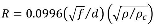
where R is resistance in ohms, f is frequency in MHz, d is the conductor diameter in inches, and ρ/ρc is the resistivity of the conductor relative to copper (assume ρ/ρc = 1 for this discussion).
The effective AC resistance of 100 ft. of our 0.109 inch diameter conductor works out to about 2.04 Ω at 5 MHz, 9.14 Ω at 100 MHz, and 26.95 Ω at 870 MHz. Recall that the DC resistance of that 100 ft length of conductor is just 0.135 Ω. The increase in the “RF resistance” (the effective AC resistance) as the frequency increases results in greater attenuation at higher frequencies compared to lower frequencies. (Side note: Because of skin effect, the cable’s center conductor does not have to be solid copper. Instead, it’s copper-clad aluminum, with the copper cladding’s thickness slightly less than 0.003 inch, sufficient for essentially all of the RF current to stay in the cladding.) The same principles discussed here also apply to the cable’s shield.
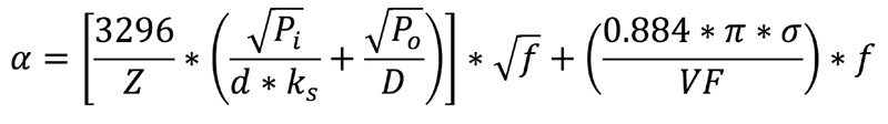
Calculating attenuation
The above formula can be used to calculate coaxial cable attenuation, but as you can see it’s a somewhat gnarly one, so I won’t try to put you to sleep showing how the formula is used.
Here’s an easier-to-remember rule-of-thumb: Coaxial cable attenuation increases approximately as the square root of frequency. In other words, if you know the attenuation at one frequency, the attenuation in decibels at four times that frequency will be approximately double the lower frequency’s attenuation. Referring back to Table 1, the attenuation of the .500 hardline coax at 211 MHz (1.09 dB/100 ft) is approximately twice what it is at 55 MHz (0.54 dB/100 ft), and the frequency difference is approximately four (actually ~3.8x).
You may have noticed that the plot in Figure 1 goes to 3 GHz. Many connector and cable manufacturers are now specifying attenuation to that frequency, in part because of the extended frequency operation supported by DOCSIS 4.0. That makes understanding attenuation all the more important!
—

Table 1. Coaxial cable attenuation-versus-frequency
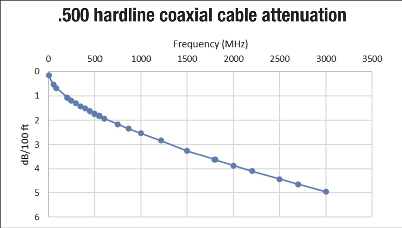
Figure 1. Plot of attenuation-versus-frequency for .500 hardline coaxial cable
 Ron Hranac
Technical Editor,
Broadband Library
rhranac@aol.com
Ron Hranac, a 48 year veteran of the cable industry, has worked on the operator and vendor side during his career. A Fellow Member of SCTE and co-founder and Associate Board Member of the organization’s Rocky Mountain Chapter, Ron was inducted into the Society’s Hall of Fame in 2010, is a co-recipient of the Chairman’s Award, an SCTE Member of the Year, and is a member of the Cable TV Pioneers Class of ’97. He received the Society’s Excellence in Standards award at Cable-Tec Expo 2016. He was recipient of the European Society for Broadband Professionals’ 2016 Tom Hall award for Outstanding Services to Broadband Engineering, and was named winner of the 2017 David Hall Award for Best Presentation. He has published hundreds of articles and papers, and has been a speaker at numerous international, national, regional, and local conferences and seminars.